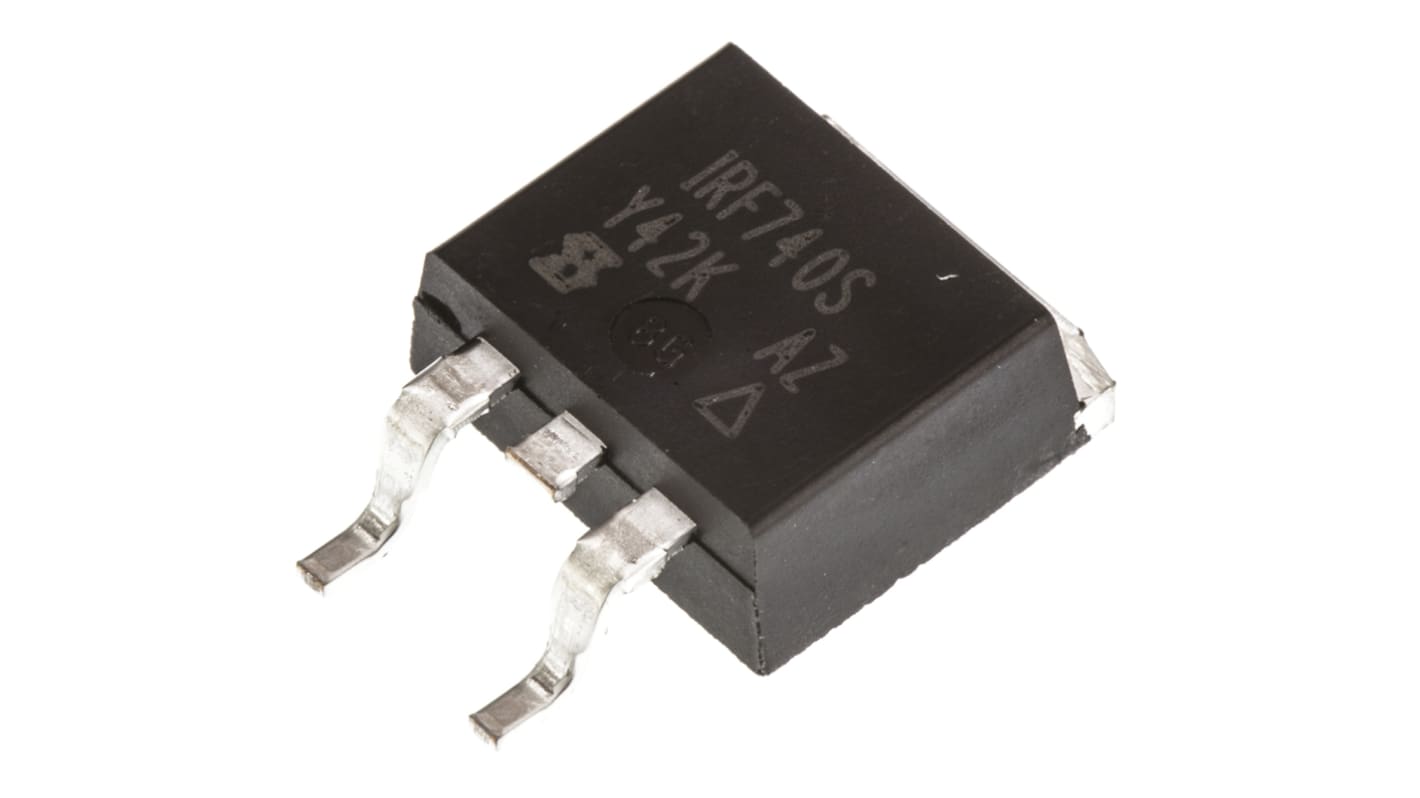
Vishay IRF740S Type N-Channel Power MOSFET, 10 A, 400 V Enhancement, 3-Pin TO-263 IRF740SPBF
- RS Stock No.:
- 542-9406
- Distrelec Article No.:
- 171-15-868
- Mfr. Part No.:
- IRF740SPBF
- Brand:
- Vishay

Bulk discount available
View bulk pricing optionsSubtotal (1 unit)*
Kr. 35,81
(exc. VAT)
Kr. 44,76
(inc. VAT)
FREE delivery for online orders over 750,00 kr
In Stock
- Plus 4 unit(s) shipping from 13 July 2026
- Plus 41 unit(s) shipping from 13 July 2026
- Plus 632 unit(s) shipping from 20 July 2026
Need more? Click ‘Check delivery dates’ to find extra stock and lead times.
Units | Per unit |
|---|---|
| 1 - 9 | Kr. 35,81 |
| 10 - 49 | Kr. 30,66 |
| 50 - 99 | Kr. 28,71 |
| 100 - 249 | Kr. 27,00 |
| 250 + | Kr. 21,74 |
*price indicative
- RS Stock No.:
- 542-9406
- Distrelec Article No.:
- 171-15-868
- Mfr. Part No.:
- IRF740SPBF
- Brand:
- Vishay
Specifications
Technical Reference
Legislation and Compliance
Product Details
Find similar products by selecting one or more attributes.
Select all | Attribute | Value |
|---|---|---|
| Brand | Vishay | |
| Product Type | Power MOSFET | |
| Channel Type | Type N | |
| Maximum Continuous Drain Current Id | 10A | |
| Maximum Drain Source Voltage Vds | 400V | |
| Series | IRF740S | |
| Package Type | TO-263 | |
| Mount Type | Surface | |
| Pin Count | 3 | |
| Maximum Drain Source Resistance Rds | 550mΩ | |
| Channel Mode | Enhancement | |
| Maximum Power Dissipation Pd | 125W | |
| Minimum Operating Temperature | -55°C | |
| Maximum Gate Source Voltage Vgs | 20V | |
| Typical Gate Charge Qg @ Vgs | 63nC | |
| Forward Voltage Vf | 2V | |
| Maximum Operating Temperature | 150°C | |
| Length | 10.67mm | |
| Standards/Approvals | RoHS | |
| Width | 9.65mm | |
| Height | 4.83mm | |
| Automotive Standard | No | |
| Select all | ||
|---|---|---|
Brand Vishay | ||
Product Type Power MOSFET | ||
Channel Type Type N | ||
Maximum Continuous Drain Current Id 10A | ||
Maximum Drain Source Voltage Vds 400V | ||
Series IRF740S | ||
Package Type TO-263 | ||
Mount Type Surface | ||
Pin Count 3 | ||
Maximum Drain Source Resistance Rds 550mΩ | ||
Channel Mode Enhancement | ||
Maximum Power Dissipation Pd 125W | ||
Minimum Operating Temperature -55°C | ||
Maximum Gate Source Voltage Vgs 20V | ||
Typical Gate Charge Qg @ Vgs 63nC | ||
Forward Voltage Vf 2V | ||
Maximum Operating Temperature 150°C | ||
Length 10.67mm | ||
Standards/Approvals RoHS | ||
Width 9.65mm | ||
Height 4.83mm | ||
Automotive Standard No | ||
Vishay IRF740S Series Power MOSFET, 400V Maximum Drain Source Voltage, 10A Maximum Continuous Drain Current - IRF740SPBF
This power MOSFET is a high-voltage, N-channel enhancement device designed for surface-mount applications in industrial electronic systems. It functions as a switching transistor capable of handling substantial voltage and current in demanding environments, suitable for use where compact, board-mounted power switching is required.
Features and Benefits:
• 400V drain rating enables high-voltage switching applications • 10A continuous current supports moderate power loads • 125W power dissipation allows sustained thermal handling • 550mΩ Rds(on) reduces conduction losses in low-to-mid power circuits • 63nC typical gate charge yields predictable drive requirements • 150°C maximum operating temperature suits high-temperature environments
Applications
• Suitable for industrial motor drive switching stages • Ideal for high-voltage power converters and inverters • Used for auxiliary power supplies in automation equipment • Can be used for solid-state relay and switch modules • Used with surface-mount assemblies requiring TO-263 mounting
What mounting style does it require on a PCB?
It is supplied in a TO-263 surface-mount package with three pins designed for board-level soldering and thermal conduction to a PCB copper area.
What gate voltage limits must designers observe?
Gate-to-source voltage must not exceed 20V to avoid gate oxide stress and potential device failure.
How should thermal management be approached in designs?
Designers should use adequate copper area or heatsinking on the PCB to dissipate up to 125W under specified conditions and maintain junction temperatures below the 150°C limit.
What environmental temperature range can it tolerate during operation?
The device is rated to operate down to -55°C and up to 150°C, permitting use across a wide range of ambient temperatures.
What characteristic affects switching drive sizing?
The typical gate charge of 63nC determines the drive current and transition times required from the gate driver to achieve the desired switching speed.
Related links
- Vishay IRF740S Type N-Channel MOSFET 400 V Enhancement, 3-Pin TO-263
- Vishay IRF Type N-Channel MOSFET 400 V Enhancement, 3-Pin TO-220 IRF740PBF
- Vishay IRF740A Type N-Channel MOSFET 400 V Enhancement, 3-Pin TO-220 IRF740APBF
- Vishay IRF740LC Type N-Channel MOSFET 400 V Enhancement, 3-Pin TO-220 IRF740LCPBF
- Vishay IRF Type N-Channel MOSFET 400 V Enhancement, 3-Pin TO-220
- Vishay IRF740A Type N-Channel MOSFET 400 V Enhancement, 3-Pin TO-220
- Vishay IRF740LC Type N-Channel MOSFET 400 V Enhancement, 3-Pin TO-220
- Vishay Type N-Channel MOSFET 400 V, 3-Pin TO-263