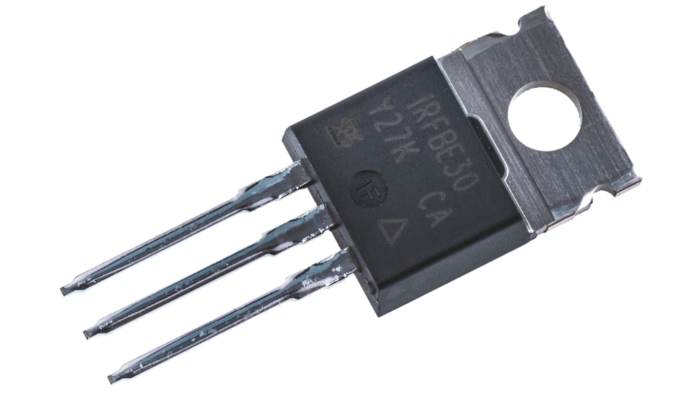
Vishay IRFBE30 Type N-Channel Power MOSFET, 4.1 A, 800 V Enhancement, 3-Pin TO-220AB IRFBE30PBF
- RS Stock No.:
- 541-1124
- Distrelec Article No.:
- 171-15-208
- Mfr. Part No.:
- IRFBE30PBF
- Brand:
- Vishay

Bulk discount available
View bulk pricing optionsSubtotal (1 unit)*
Kr. 30,66
(exc. VAT)
Kr. 38,32
(inc. VAT)
FREE delivery for online orders over 750,00 kr
In Stock
- Plus 134 unit(s) shipping from 13 July 2026
- Plus 137 unit(s) shipping from 13 July 2026
- Plus 1 382 unit(s) shipping from 20 July 2026
Need more? Click ‘Check delivery dates’ to find extra stock and lead times.
Units | Per unit |
|---|---|
| 1 - 9 | Kr. 30,66 |
| 10 - 49 | Kr. 29,63 |
| 50 - 99 | Kr. 28,37 |
| 100 - 249 | Kr. 26,77 |
| 250 + | Kr. 25,51 |
*price indicative
- RS Stock No.:
- 541-1124
- Distrelec Article No.:
- 171-15-208
- Mfr. Part No.:
- IRFBE30PBF
- Brand:
- Vishay
Specifications
Technical Reference
Legislation and Compliance
Product Details
Find similar products by selecting one or more attributes.
Select all | Attribute | Value |
|---|---|---|
| Brand | Vishay | |
| Product Type | Power MOSFET | |
| Channel Type | Type N | |
| Maximum Continuous Drain Current Id | 4.1A | |
| Maximum Drain Source Voltage Vds | 800V | |
| Series | IRFBE30 | |
| Package Type | TO-220AB | |
| Mount Type | Through Hole | |
| Pin Count | 3 | |
| Maximum Drain Source Resistance Rds | 3Ω | |
| Channel Mode | Enhancement | |
| Maximum Gate Source Voltage Vgs | 20V | |
| Maximum Power Dissipation Pd | 125W | |
| Minimum Operating Temperature | -55°C | |
| Forward Voltage Vf | 1.8V | |
| Typical Gate Charge Qg @ Vgs | 78nC | |
| Maximum Operating Temperature | 150°C | |
| Height | 9.01mm | |
| Length | 10.41mm | |
| Width | 4.7mm | |
| Standards/Approvals | RoHS | |
| Automotive Standard | No | |
| Select all | ||
|---|---|---|
Brand Vishay | ||
Product Type Power MOSFET | ||
Channel Type Type N | ||
Maximum Continuous Drain Current Id 4.1A | ||
Maximum Drain Source Voltage Vds 800V | ||
Series IRFBE30 | ||
Package Type TO-220AB | ||
Mount Type Through Hole | ||
Pin Count 3 | ||
Maximum Drain Source Resistance Rds 3Ω | ||
Channel Mode Enhancement | ||
Maximum Gate Source Voltage Vgs 20V | ||
Maximum Power Dissipation Pd 125W | ||
Minimum Operating Temperature -55°C | ||
Forward Voltage Vf 1.8V | ||
Typical Gate Charge Qg @ Vgs 78nC | ||
Maximum Operating Temperature 150°C | ||
Height 9.01mm | ||
Length 10.41mm | ||
Width 4.7mm | ||
Standards/Approvals RoHS | ||
Automotive Standard No | ||
Vishay IRFBE30 Series Power MOSFET, 800V Drain Source Voltage, 4.1A Continuous Drain Current - IRFBE30PBF
This power MOSFET is a through‑hole N‑channel transistor designed for switching and power control in industrial electronics. It operates as an enhancement‑mode device suitable for high‑voltage applications, offering a combination of voltage handling and gate‑drive capability for demanding electrical systems.
Features and Benefits:
• 800V drain‑source voltage enables high‑voltage switching applications • 4.1A continuous drain current supports moderate load currents • 3 Ω maximum Rds reduces current loss during conduction • 78 nC typical gate charge allows predictable switching behaviour • 125W power dissipation manages thermal stress in power circuits • -55 °C to 150 °C operating range endures wide temperature extremes
Applications
• Suitable for high‑voltage power supplies and converters • Ideal for industrial motor drive switching stages • Used for solid‑state relay and protection circuitry • Can be used for load switching in automation panels
What gate voltage limits should I observe during design?
Gate drive must remain within ±20V maximum relative to source to prevent gate‑oxide stress.
How should thermal management be approached on a PCB?
Use a heatsink on the TO‑220AB package or a thermally conductive mounting solution to dissipate up to 125W of power under rated conditions.
What switching characteristics affect EMI in my design?
The typical gate charge of 78 nC at the specified gate drive influences rise and fall times, impacting switching transitions and electromagnetic emissions.
Is this device suitable for surface‑mounting techniques?
It is supplied in a TO‑220AB through‑hole package intended for mechanical mounting and conventional through‑hole assembly.
Related links
- Vishay IRFBE Type N-Channel MOSFET 800 V Enhancement, 3-Pin TO-220
- Vishay IRFBE Type N-Channel MOSFET 800 V Enhancement, 3-Pin TO-220
- Vishay IRFBE Type N-Channel MOSFET 800 V Enhancement, 3-Pin TO-220 IRFBE20PBF
- Vishay IRFBE Type N-Channel Power MOSFET 900 V Enhancement, 3-Pin TO-220AB
- Vishay IRFBE Type N-Channel Power MOSFET 900 V Enhancement, 3-Pin TO-220AB
- Vishay IRFBE Type N-Channel Power MOSFET 900 V Enhancement, 3-Pin TO-220AB IRFBF30PBF
- Vishay IRFBE Type N-Channel Power MOSFET 900 V Enhancement, 3-Pin TO-220AB IRFBF20PBF
- Vishay SiHU4N80AE Type N-Channel MOSFET 800 V Enhancement, 3-Pin IPAK SIHU4N80AE-GE3